Tuesday, March 8, 2016

Coil Winder Contraption

I needed a quick way to wind some coils for my motorcycle
Why, you might ask? Well, because I was tired of having a 6V system with all its downsides. Fortunately motelek.net has a wealth of information on how to upgrade my old Bosch ignition-and-power-system (there has got to be a better word for this, I am sure of it) to 12V, which has a lot of benefits (proper light in the front, I can use LEDs for tail- and brakelight etc).
But, this means I had to rewind two coils. Since I am somewhat lazy I threw together this machine with parts that I had lying around. It is powered by a sewing machine motor, which I had to significantly gear down, since it tops out at 6000rpm - waaaay too fast. I used some MDF discs that I had kept for ages in a cardboard box, various rubber bands and threads, and some rubbish MDF pieces.
It is important to keep count of your windings, so I rigged an Arduino to the system: every revolution a switch is momentarily closed, the Arduino registers this impulse, increases a counter by 1, and sends the counter value to the serial monitor. Easy peasy!
Now it is a piece of cake to make the necessary 505 respectively 180 windings.

Tuesday, October 27, 2015

MSSIAH SDR Device


I built this thing called "SDR device" for the Commodore 64. With this you can load and save patches made with MSSIAH without having to use Floppy disks. The device was conceived by firestARTer, and he was nice enough to send me a pre-programmed MCU for it (which speedily arrived from Rotterdam). You will find all the information to build your own SDR device on his website.
The case is from an ancient Hewlett Packard Laserprinter accessory, which connects with a DB9-connector to the C64. There is a LCD display, an encoder with pushbutton, and a extra button.
The data gets saved on a MicroSD-card with a capacity of (wait for it...) 128 megabytes of memory.
It´s kind of funny: this is so much memory from the C64s point of view, yet such a tiny amount by todays standards.
The C64 also has a 6,3mm jack for audio out, and a cinch connector for video out (so much easier on the eyes than using the antenna output).
The SDR device works remarkably well - and on a sidenote: MSSIAH is the only program so far that uses this storage medium.

Friday, January 11, 2013

Akai S3000 MIDI + SCSI Retrofit

I really like my Akai S3000. It is an oldschool beast of a sampler, and if you know your way around the menu structure, you're able to get complex sounds in very little time.
However, there were a few things that annoyed me a bit. 
Here is what I did:

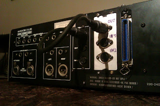
First of all, I really wanted a second MIDI input. Constantly replugging Midi cables (while crawling in the narrow space behind the rack) is not my idea of fun. I made an addon card based on the UCApps.de Midi Merger (sorry, no direct link possible). It does exactly what the name suggests: it merges two MIDI inputs to a single output. Now I route that output to the MIDI IN of the Akai with a short cable - voila! - two MIDI inputs. (Yes, I know in the first picture the two optocouplers are not yet in their sockets...) Now I can connect my hardware sequencer and my MIDI interface at the same time, and I can use them separately or in combination.

The other major thing was the floppy drive. Juggling all those 1.44MB disks is sooo 90ies, and when I came across an old SCSI Harddisk (Quantum ProDrive with whopping 120MB - that is megabytes) I put it in the sampler. This gave me a bit of an headache, as there is NO documentation for the S3000 on the net whatsoever (only for the S3000XL, which is a different animal). I won't go into detail about the hellish nightmares here, but let me say this: why on earth did Akai decide to use standard SCSI cables, but then they build a sampler that requires them to be plugged in backwards??? We'll never know.) Anyway, after waaaay to much time experimenting and reading obscure forum posts from like 1997 or so, I got it to work by filing off the notch on the cable that (kinda rightfully) forces you to plug it in only one way.

I could have been happy, but there is always a ...but

When you turn on the sampler, it will boot its OS from a ROM, then it will look for an updated OS on the disk, and then boot into that. Only, the old and slow HDD never was ready spinning up at that point, which always gave me a "disk not ready" error. I always had to load the updated OS manually. How annoying.

I added a small 555-based "delayed power on" circuit to the addon card. This handy dandy thing closes a relay after 3 seconds. This relay actually switches the +5V power line going to the mainboard.
When you power on the Akai now the following is happening: power is applied to the harddisk, which starts spinning. 3 seconds pass, the relay (the small orange box on the back of the circuit board) closes with a CLICK. Only now the mainboard is powered on, thus the sampler starts to boot. Because the HDD now has had some extra time to get ready, the S3000 can happily read the OS from the disk and boot into that. READY.
I am also thinking of making the frontpanel detachable like on the S6000, but that is for another day.

Tuesday, January 8, 2013

Böhm Soundlab Multi Module

This one is a bit embarrassing... A friend of mine is a proud owner of a Böhm Soundlab Modular Synthesizer. About 300 or so were ever made, and at least half of them were destroyed when the warehouse of the german Böhm company burned down. Needless to say, this thing is quite rare, and modules are hard to come by.
Now, the synth comes in this somewhat flimsy hardshell suitcase, and this particular specimen had some unused space that begged to be filled in a meaningful way.
My friend asked me if I could help, and I said "Yes!" - I offered to make a module with an 8-step sequencer, a state variable VCF (LM137000 anyone?), a double CV Inverter and a double "gender bender" (to convert between banana jack and 6,3mm mono plugs); thus making the most out of the available space.
My friend said "GREAT!" and we agreed on a timeframe of about 3 months or so. You might get an idea where this is going... I started with the module and got it finished to about 85% within the first 2 months... then I moved... and did not have time to work on it....then I moved again... putting it away safely... then I thought about continuing my work (but found good excuses not to)... and finally, TWO-AND-A-FUCKING-HALF-YEARS-LATER, I finished the module (took another whopping 4 hours. I could have done it waaaaaaay earlier....). 
I had some trouble with the sequencer, it is based on the popular "Baby 10" design, and unfortunately that means the gate signals of consecutive steps are joined. Of course, we can not have that. I made it so that rather than gate signals, triggers are spat out, which in return can drive the envelope generators of the synth. It works amazingly well, and I am glad I got this one off my back. It gnawed at my conscience far too long.. but fortunately my friend is very forgiving and never really doubted me (he said so, it must be true!)
And yes, that is a 9mm shell next to the Resonance knob: I put a hole in the panel where I should not have, with a 9mm diameter. The shell just happened to lie around in the streets of Neukölln, Berlin, and it fitted perfectly. So there!

606 rescued

A friend of a friend had me repair his 606. The Bassdrum was not working, and someone added some nonfunctional modifications, which were executed rather crudely. I mean, if you are about to drill holes in an enclosure, at least make sure they line up properly! All in all, the machine was in a really bad shape. It could not even be programmed properly, because most of the switches were bouncing or not reacting at all.
After getting the Bassdrum working, I took out the existing mods and added some of my own: in the top left is BD pitch, top right are snare pitch, snare snappy and snare decay. Because of the aforementioned misaligned holes I put a piece of black plastic under the knobs as sort of a cover up. 
To round it all off I installed a Technology Transplant replacement switchboard and replacement volume pots. Beware! The Technology Transplant kit is not exactly living up to its expectations: the switches on it are definitely NOT new, as they had solder residue all over them, and on two of them even one of the four legs were broken off! Also they, too, were badly aligned, which means that when I put the switchcaps on them and assembled the 606, lots of the keys got stuck in the enclosure because there was not enough tolerance. I had to resolder at least half of the switches.
Anyhow, the 606 is working beautifully now, the owner is happy, so am I. Bumblebee.

Sunday, July 4, 2010

Gristleizer

Throbbing Gristle is a quite influential Industrial band. Part of what makes their sound unique is the infamous Gristleizer, a distortion unit built by bandmember Chris Carter. It has a LFO with four waveforms which controls a VCF or a VCA. There have been numerous DIY clones and there is even a commercial re-issue available (for about 400 USD, which I find a little steep).
User Taylor from the electro-music.com forums (I love that forum. Honestly.) offered a PCB for a Gristleizer clone, and I ordered one.
It has all the original features PLUS an output for the LFO - which means the thing integrates rather nicely into my modular synth. The input / output jacks are located on the front panel for that very reason. The panel is aluminum, the case itself a mixture of sheet metal, plywood and loads of gaffa tape.

Tuesday, June 29, 2010

TR 505 XL

This is what happens when you give me a TR 505.
The 505 is a digital drummachine made by Roland. It has a nice, easy-to-use sequencer, a big display, full MIDI capabilities and some of the most boring sounds that you'll ever hear...
Time to mod it, I'd say!
It now sports single outputs (1/4") and trigger outs (1/8"). Especially the trigger outputs are quite handy for owners of a modular synth... the 505 will work as a MIDI-to-trigger converter too!
Also the sounds are now tunable - I added 8 new oscillators (this time 40106 based, unlike the 555 based ones on my TR 707) to accomplish this.
I also added volume controls, so now there are 16 new knobs on the front panel. The volume controls are doubling as a"crunch" control, which goes like this: the maximum volume is reached at the 12 o´clock position (and the potentiometers have a center detent to reflect this), turning the knob further to the right will overdrive the internal mixer stage a bit, resulting in a slightly distorted sound. This adds a nice punch and grit! Due to the way the mixer stage is designed this will only work on the main outputs.
Most of the necessary informationon how to do these mods can be had from the Burnkit2600 TR505 page, so thanks to those guys!
All that stuff did not fit into the stock enclosure, I had to make some side cheeks out of stained plywood in order to raise the height of the case by 3cm.

Check the sound sample below for a glimpse of what this machine sounds like. No FX, no overdubs, no EQ used - recorded straight from the master output.


Monday, June 21, 2010

x0xb0x, again

So here it is, my second x0xb0x. This one has been finished for ages, but only today it occured to me that pictures would be nice.
It is completely self sourced, which means that I did not buy a kit but aquired all parts separately. Likewise there is no official Adafruit serial number.

The frontpanel was made by Schaeffer Apparatebau in Berlin - this one has far too many modifications for the "stock" panel. The legend was made with Lazertran.


The mods are:
PWM for the square wave
Accent Sweep Speed selectable between fast, normal and slow
Accent Decay control
Filter Overdrive with "color" knob
Bass Boost, Resonance Boost (with separate pushbutton switch and LED indicator)
"Eternal Bliss" - this is a combined Gate On Forever / Envelope On Forever to get those liquid acid lines
Filter Modulation with selectable source (square, saw, VCA) and two modes (buffered / unbuffered)
Envelope Retrigger button
VCO out / Filter in on TRS socket
orange / amber 3mm LEDs
Sokk0s 1.9 operating system

Sunday, February 7, 2010

STOMPIT - Dual FX Pedal Level Converter

Any seasoned Synthetisist knows that the voltage levels in your modular synths are much higher than the ones you'd feed into stompboxes. So, if you patch your VCO straight into, for example, your Boss FX pedal, you will get some nasty overdriving and clipping. Mind you, this distortion actually might be nice, but not desired at all times.
My good pal Waktu Loopa asked me if I'd be able to help him getting his levels right. My solution is the device pictured below: a dual FX pedal level converter. It's made to fit in his Doepfer A-100 modular system and should work nicely with his collection of stompboxes from Orion Effekte. (I tested it with the Benjamuff PI featured in my previous post.)
I designed the PCB and the frontpanel myself whilst the circuit is inspired by the invaluable genius that is Ken Stone.
The keen eye might wonder why there are some odd componends on the circuit board, most notably the HUGE 2W resistors. Easy: I am a sexy Recyclotron and so I used what I had on hand. That sometimes means that I pull components from junk electronics (always remember: recycle or die)
Because I am such a nice guy I wrote him a manual as well (he's stupid and I had a lazy sunday evening to waste). Now all that is left is to do is to actually send him the thing. As much as I hate to part with the module -I am sure it'll be in good hands.

Tuesday, August 18, 2009

Stompbox!

My good friend Benni turned 30 the other day.
Since he is an avid guitar player (and the other half of our Hardcore Electro Country Band Dezombiefied) I just had to give him something relating to that.
So here it is, the BENJAMUFF PI.
Check the Big Muff Museum if you still dont get it...